Voltage fluctuation always occurs in the electrical supply system. Due to voltage fluctuation, the life of electrical equipment consumed electricity is shorted really. To solve this problem, an automatic voltage stabilizer is needed for domestic and industries. Both single-phase and three phases are available. This article intends to know that automatic voltage stabilizer plays an efficient role in all type of load i.e. resistive, inductive, and capacitive loads. This article presents a control circuit for an automatic servo-based voltage stabilizer that provides a voltage comparator, relays, and servo-controlled motor that compare instantaneous input and output voltage.
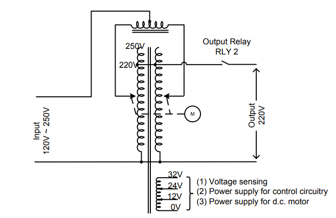
The automatic voltage stabilizer consists of two units: The measuring unit and regulating unit. In this stabilizer, toroidal type variable autotransformer is used for regulating unit and electronic control circuit is used for sensing unit. An electromechanical or servo control system is used for measuring units to sense the supply voltage. This electronic control circuit will operate within the fluctuation range from 120V to 250V. The rating of this automatic voltage stabilizer is 12kVA (single-phase) and its frequency range is 50Hz. The output sensitivity is ±1%. If the input voltage is lower than 120V or higher than 250V, the system will be automatic shutdown.

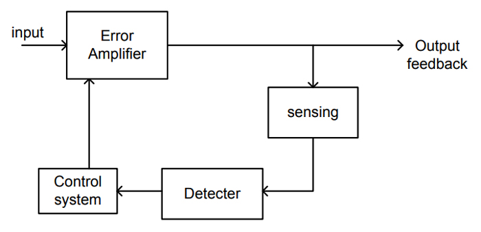
Fig. 1 shown below is the block diagram and circuit diagram of the automatic servo control voltage stabilizer connected to an appliance or load. The stabilizer sizes generally with its rating, which is given in kVA.
The regulating unit consists of a toroidal type variable autotransformer. The purpose of the regulating unit is that of acting under the signal from the measuring unit in such a manner as to correct the output voltage of the stabilizer, as near as possible, a constant or predetermined value. The measuring unit includes a control circuit. The function of the measuring unit is that of detecting a change in the input or output voltage of the automatic voltage stabilizer and producing a signal to operate the regulating unit.

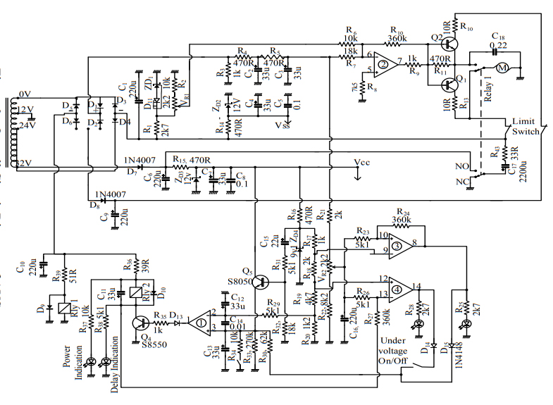
The overall circuit diagram of the control circuit for AVS is shown in figure 3. The transformer steps down the AC source voltage to 12V. Then, the transformer output is rectified by a bridge rectifier. The rectifier output voltage is filtered by a capacitor. In this circuit, LM324 is used as a comparator and indicator. The noninverting input (-Vin) the op-amp is greater than the inverting input (-Vin) the op-amp is ON-state. At normal conditions, positive voltage sensing only. If VR1 is adjusted so that when the output AC voltage is 220V, the op-amp output is zero. Op-amp (3) is used for over-voltage conditions. It is connected as the voltage comparator. When transistor Q2 base receives forward bias and Q2 goes ‘ON’ motor runs in the direction to raise the voltage. When transistor Q1 base is forward biased and Q1 goes ‘ON’ motor runs in the other direction to lower voltage. After the preset time, op-amp output swings positive and releases the relay. The control system is automatically shut down when the voltage fluctuation is lower than 120V and higher than 250V.

Figure 3 . Overall Circuit Diagram of AVS
