A voltage stabilizer is a power supply circuit or power supply device that can automatically adjust the output voltage. Its function is to stabilize the power supply voltage that fluctuates greatly and does not meet the requirements of electrical equipment within its set value range so that various circuits or electrical appliances can be stabilized. The equipment can work normally under the rated working voltage. The following is an introduction to how to use the voltage stabilizer correctly.
Voltage stabilizer using guide
- Open the package and check whether the enclosure, meter, switch, indicator light, button, wiring terminal, etc. of the stabilizer are damaged or not. Only those without damage can be used.
- Insert (or connect) the input terminal to the power distribution board, and install a fuse that matches the power of the voltage stabilizer on the user power distribution board to ensure the safety of electricity use.

- Connect the power supply of the electrical equipment to the output terminal of the stabilizer, pay attention to whether the applicable voltage of the electrical appliance is 220V or 110V, and do not connect it wrongly.
- Turn on the power switch of the voltage stabilizer first, the working indicator and the delay indicator are on, there is no power output, and the power will be sent after 3-7 seconds, and observe whether the indicator light indicates 220V normally. When the output voltage is normal (about 220V), turn on the power switch of the electrical equipment. The voltage stabilizer can automatically adjust the voltage and supply power normally.
- The wire connected to the voltage stabilizer should have enough cross-section to prevent heat generation and reduce voltage drop. Voltage stabilizers with a capacity of more than 2KVA are connected by terminals. A single copper wire should be used, and the terminal screws should be tightened as much as possible to prevent the connection from heating.
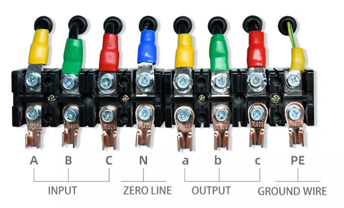
- The left three terminals A, B, and C of the three-phase voltage stabilizer are connected to the input three-phase phase line (live wire), the right three terminals X, Y, Z are connected to the load, and the two middle terminals are connected to the input and output shared neutral line. The wiring of the single-phase voltage stabilizer is as shown on the terminal cover.
- The voltage detection button on the panel of the three-phase voltage stabilizer indicates the AB and AC phase line voltages (380V) when pressed in and out respectively. The button and universal conversion can only be regarded as whether the two voltages are in normal use.
- Whether it is a single-phase or three-phase voltage stabilizer, after connecting all the input and output lines, the power switch of the load (electrical appliance) should be turned off first, and then the voltage stabilizer should be turned on. After checking that the output voltage is normal, turn on the power switch of the load device.

Voltage stabilizer safety device
The voltage stabilizer below 3KVA (such as ATO 500VA stabilizer for home) uses a fuse for overload or short circuit protection, and the AC voltage stabilizer above 5KVA uses a small circuit breaker or a small air switch for overload or short circuit protection. The load and voltage regulator should be checked off.
Voltage stabilizer overvoltage protection
When the output voltage exceeds the protection value of the voltage stabilizer (the phase voltage protection value is adjusted to 250V±5V at the factory), the voltage stabilizer will automatically protect. When the output voltage of the voltage stabilizer is reduced or cut off, and the overvoltage indicator light is on, the user should immediately shut down and check the grid voltage or the voltage stabilizer. When the voltage stabilizer is working, if there is a jitter in the output voltage, it may be that the capacitive or inductive load is too heavy. The user can adjust the gear position of the switch on the circuit board in the chassis to eliminate the jitter phenomenon (please turn off the load when adjusting). When the machine leaves the factory, the switch is in a normal state, and the user should not move it without authorization. If the jitter phenomenon cannot be eliminated, it may be caused by the too large internal resistance of the input grid line or serious input waveform distortion. Please check the line diameter of the grid line and the quality of the connection points and solve them.
If the voltage stabilizer has been in the overvoltage protection state after starting, please check whether the voltage regulating potentiometer is adjusted normally and whether the grid voltage exceeds the normal working voltage regulation range of the voltage stabilizer. Turn on the switch of the voltage stabilizer, and then turn on the electrical equipment after the output voltage is stable, turn off the power, and proceed according to the reverse procedure.
