Basic
A three-phase static voltage stabilizer is a power electronics-based device that protects the non-linear, complex loads by maintaining the output voltage within permissible limits irrespective of the voltage sags, voltage swell, transient voltage, harmonics, overvoltage, under-voltage, and phase unbalance. When such events occur in power systems the whole system can get collapsed. The operating principle of semiconductor devices/switches in voltage stabilizers is based on pulse width modulation. The duty cycle of input pulses to these switches is adjusted by using the Space Vector Pulse Width Modulation (SVPWM) technique which provides better results over Sinusoidal Pulse Width Modulation (SPWM).
Working principle
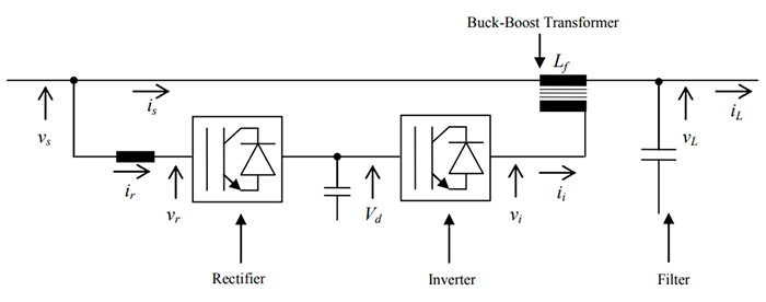
Fig.1 shows the block diagram of the static voltage stabilizer. It consists of a rectifier, inverter, buck-boost transformer, and filter. The basic principle of operation of the static voltage stabilizer is to keep the output voltage i.e. load voltage within permissible limits irrespective of the changes in the input voltage. When the input voltage increases or decreases within a certain limit, the control scheme performs the operation in such a way that incoming voltage increases or decreases from its value to acceptable output voltage i.e. provide the energy source to get the required output voltage. This energy source can be implemented by taking the energy from the incoming supply (rectifier). The direction of the current flow as shown in the block diagram is bidirectional depending upon the input voltage behavior i.e. increasing or decreasing from the expected output voltage.

When Vs is less than the required VL, the power converter produces a voltage across the transformer in a direction such that this voltage adds to the input voltage to get desired output voltage (i.e. the current flows from the input side to the output side through the rectifier and inverter path). When Vs is more than the desired VL, the power converter produces a voltage in a direction such that this voltage is subtracted from the input voltage to get desired output voltage (i.e. the current flows from the output side to the input side through the inverter and rectifier path).

Energy Unit
The energy unit in the static voltage stabilizer plays the important role of providing a sufficient amount of energy so that the load voltage will be within acceptable limits. The different types of energy storage units are energy supply using a Non-Controlled rectifier, energy supply using a Controlled Rectifier, Accumulator cell, etc. In the case of a Non-Controlled rectifier, only one-way current flow is possible, so this problem is solved by using a Controlled Rectifier. Nowadays Controlled Rectifier strategy is most popular because of its ability to remove harmonics since it acts as the active filter and can provide unity Power factor correction.
Inverter
The inverter is used to produce the required output voltage by using the DC voltage provided by the Energy storage unit. The different Inverter structures are semi-bridge, full-bridge, and push-pull Inverter. Full-bridge Inverter is most commonly used because it is easy to implement and removes the problem of zero vector switching which is important in three-phase systems but it suffers from the bridge-arm shoot-through problem. In the push-pull inverter structure in each of the three arms, only one semiconductor/switching device is on at any given time, so this structure eliminates the problem of bridge-arm shoot-through.
Filter
Semiconductor devices like IGBTs, MOSFETs, etc. are used as switching devices in rectifier and inverter parts. Since these devices are having nonlinear characteristics, they produce high-frequency harmonics which is undesirable in the case of complex loads. To solve this problem filter is required which can be placed before or after the buck-boost transformer. The rating of the filter is decided by the requirement of output load voltage and available input voltage range.
Buck-Boost Transformer
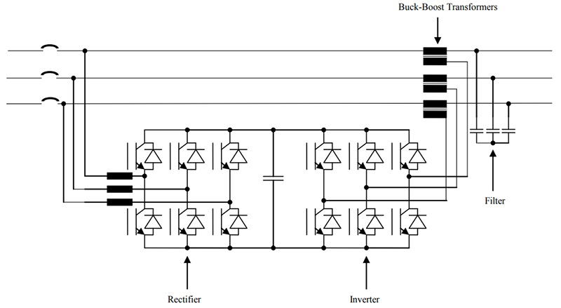
Three single-phase transformers are used for buck-boost purposes depending on the supply voltage. The transformer rating i.e. turns ratio design is important because the current direction is bidirectional.
